
Week 12 : Interface and application programming
the assignments for this week are:
The individual assignment
- Write an application that interfaces a user with an input &/or output device that you made!
The group assignment:
- Compare as many tool options as possible
Group Assignment:
The direct link for the group assignmentIndividual Assignment
Well, for this week we had to make an application that communicate with an input or output device, and since me and my roommates(both of them are inrolled in the fabacademy, so Trouble X 3 here.
Since most of the assignments that we did , we didn't get the chance to use anything except for the online simulation!
But luckliy, we got to borrow an arduino for us three! and yeah fially we get to work with it!
NOTE: the problem is that we didn't find any wide options for the sensors:
So for this week we had to work on an app that communicates with those devices!
And yeah it's my first time that I'm working with this!
But first of all, we decided to work with the python language(under the instructions of our instructor who said to us that learning python helps in many other things, this kind of languages is ,not in a way, a very limited language and by learning it , but it opens for you many things in the futur ) )
But befoe that we had to install the PYCHARM which is an integrated development environment for python!
We tried something so "BANAL" as a first step!
import tkinter as tk

class Application(tk.Frame):

    def __init__(self, master=None):
        super().__init__(master)
        self.grid(row=0, column=0)
        self.create_widgets()
        master.resizable(False, False)

    def create_widgets(self):
        self.tkLabel = tk.Label(self)
        self.tkLabel["text"] = "3asslema"
        self.tkLabel.grid(row=0, column=0)

        self.tkEntry = tk.Entry(self)
        self.tkEntry.grid(row=1, column=0)

        self.tkButton1 = tk.Button(self)
        self.tkButton1["text"] = "Make me WORK"
        self.tkButton1["command"] = self.readText
        self.tkButton1.grid(row=2, column=0)

        self.tkButton2 = tk.Button(self)
        self.tkButton2["text"] = "Make me STOP"
        self.tkButton2["command"] = self.readText
        self.tkButton2.grid(row=3, column=0)

        self.tkButton3 = tk.Button(self, text="X", fg="blue", command=self.master.destroy)
        self.tkButton3.grid(row=4, column=0)

    def readText(self):
        print(self.tkEntry.get())


root = tk.Tk()
app = Application(master=root)
app.master.title("Fabacademy 2020")
app.mainloop()
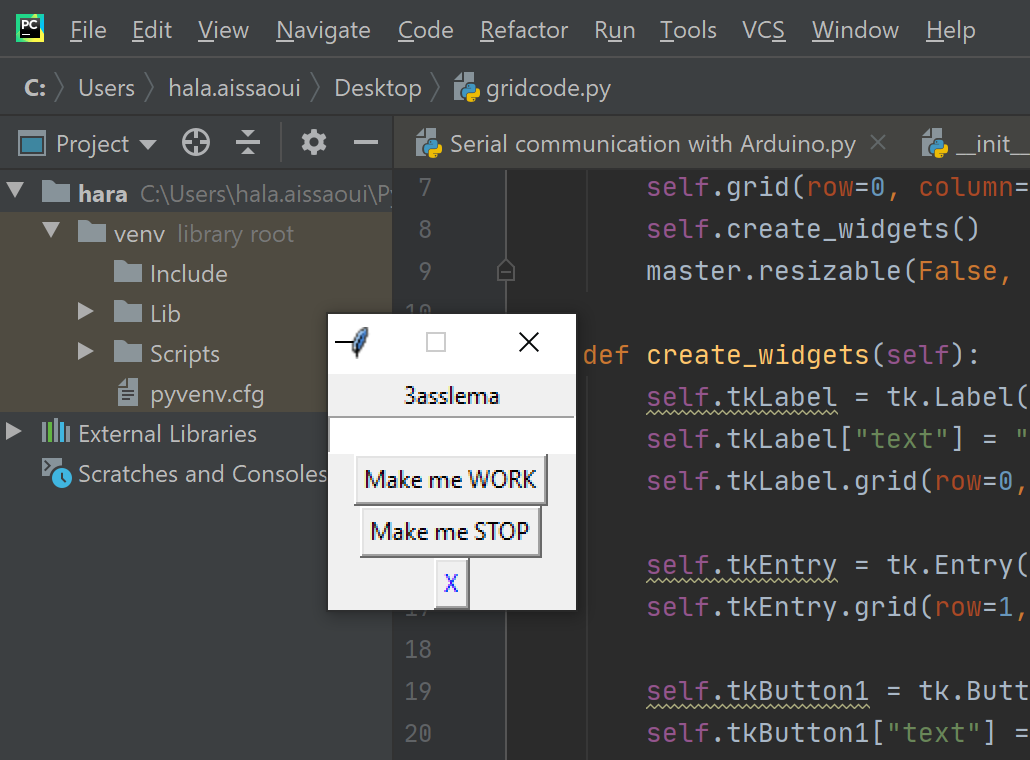
Application test
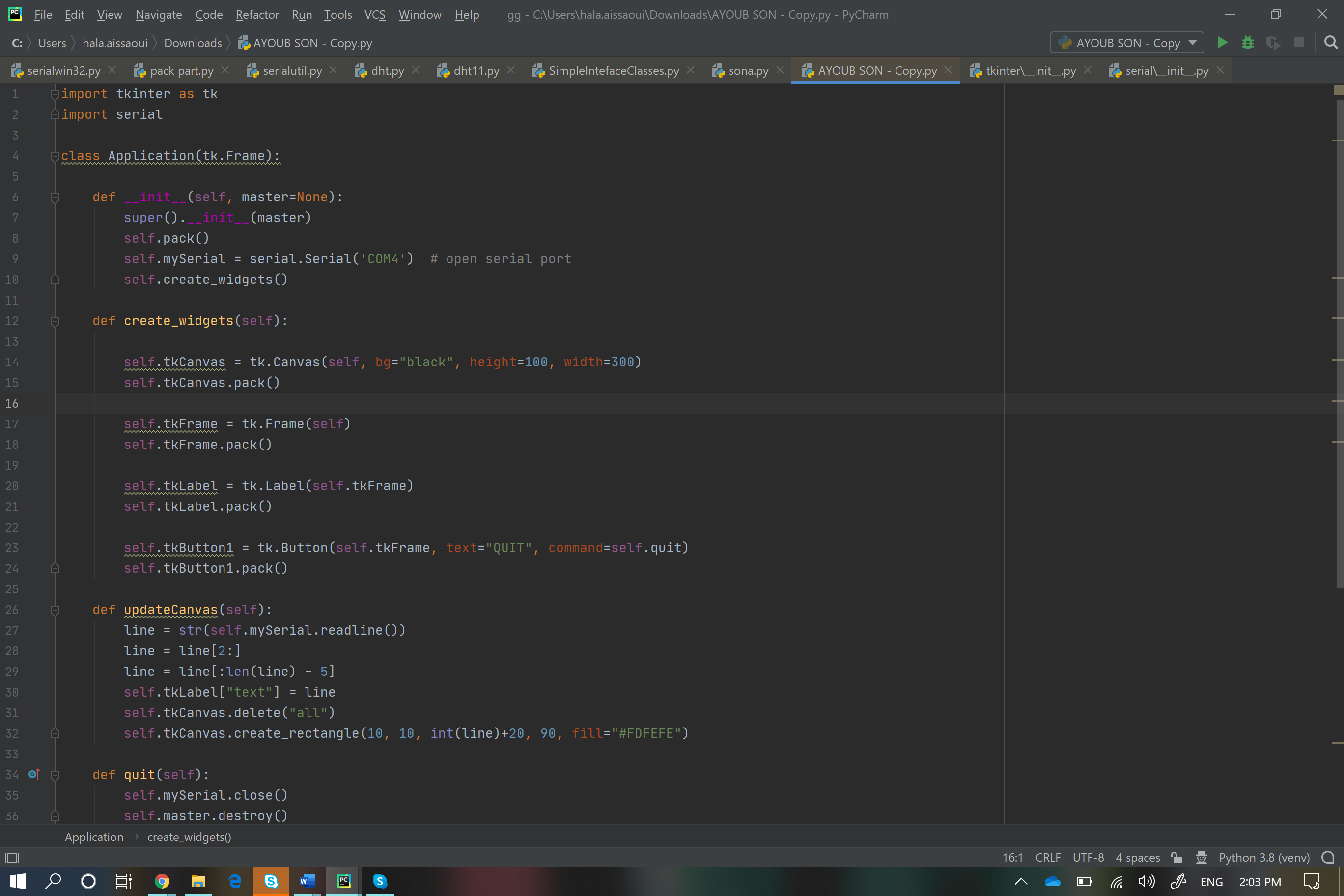
COMMUNICATION WITH THE ARDUINO
LED switchAfter uploading the code( the code is mainly about controlling the LED and make it blink just by sending a kind of message:L)! The python code works under the same principle, so by clicking on the switch buttom, you can control it!!
import tkinter as tk
import serial

class Application(tk.Frame):

    def __init__(self, master=None):
        super().__init__(master)
        self.pack()
        self.mySerial = serial.Serial('COM4')  # open serial port
        self.create_widgets()

    def create_widgets(self):

        self.tkLabel = tk.Label(self)
        self.tkLabel.pack()

        self.tkButton1 = tk.Button(self, text="On Me/Off Me!", command=self.sendData)
        self.tkButton1.pack()

        self.tkButton2 = tk.Button(self, text="Close Me", command=self.quit)
        self.tkButton2.pack()

    def sendData(self):
        self.mySerial.write("L".encode())

    def quit(self):
        self.mySerial.close()
        self.master.destroy()


root = tk.Tk()
app = Application(master=root)
app.master.title("LED Blink Blink ")
app.master.geometry("900x600")
app.mainloop()
MANIFESTATION
UPDATE
Since we made our Boards for the INPUT and OUTPUT weeks so why don't we try other APPS like
MIT App InventorPROCESSING
And I choose to work with Processing here
since it seemed it was so easy to use.
DHT
So my main aim here is to create a GUI to visualise the Temperature and Humidity.First things first,
I did the same thing as I usually do when I upload the Arduino code
since I will be using the Arduino as my programmer here, I had to do the old fashioned wiring.
and to make some simple modification in the Arduino App;
Tools>Board>Arduino AVR Boards>Arduino Pro or Pro mini After the hardware part is all set, next step is to write a code for Arduino to read the DHT11 sensor data and to creat a nice GUI in Processing to visualize temperature and humidity values coming from the sensor through the serial port.
Here we upload two different codes to the board,
the Arduino code
#include <SimpleDHT.h>
int pinDHT11 = A0;
SimpleDHT11 dht11;

void setup() {
Serial.begin(9600);
}
void loop() {
float temperature = 0;
float humidity = 0;
int err = SimpleDHTErrSuccess;
if ((err = dht11.read2(pinDHT11, &temperature, &humidity, NULL)) != SimpleDHTErrSuccess) {
Serial.print("Read DHT11 failed, err="); Serial.println(err);delay(2000);
return;
}

Serial.print((float)temperature);
Serial.print(",");
Serial.println((float)humidity);
delay(2500);
}
Processing code
import meter.*;

import meter.*;
import processing.serial.*;

Serial port;
String[] list;

Meter m, m2;

void setup() {
  size(950, 400);
  background(0);

  port = new Serial(this, "COM7", 9600);

  fill(120, 50, 0);
  m = new Meter(this, 25, 100);
  // Adjust font color of meter value
  m.setTitleFontSize(20);
  m.setTitleFontName("Arial bold");
  m.setTitle("Temperature (C)");
  m.setDisplayDigitalMeterValue(true);

  // Meter Scale
  String[] scaleLabelsT = {"0", "10", "20", "30", "40", "50", "60", "70", "80"};
  m.setScaleLabels(scaleLabelsT);
  m.setScaleFontSize(18);
  m.setScaleFontName("Times New Roman bold");
  m.setScaleFontColor(color(200, 30, 70));

  m.setArcColor(color(141, 113, 178));
  m.setArcThickness(10);
  m.setMaxScaleValue(80);

  m.setNeedleThickness(3);

  m.setMinInputSignal(0);
  m.setMaxInputSignal(80);

  // A second meter for reference
  int mx = m.getMeterX();
  int my = m.getMeterY();
  int mw = m.getMeterWidth();

  m2 = new Meter(this, mx + mw + 20, my);
  m2.setTitleFontSize(20);
  m2.setTitleFontName("Arial bold");
  m2.setTitle("Humidity (%)");
  m2.setDisplayDigitalMeterValue(true);

  String[] scaleLabelsH = {"0", "10", "20", "30", "40", "50", "60", "70", "80", "90", "100"};
  m2.setScaleLabels(scaleLabelsH);
  m2.setScaleFontSize(18);
  m2.setScaleFontName("Times New Roman bold");
  m2.setScaleFontColor(color(200, 30, 70));

  m2.setArcColor(color(141, 113, 178));
  m2.setArcThickness(10);
  m2.setMaxScaleValue(100);

  m2.setNeedleThickness(3);

  m2.setMinInputSignal(0);
  m2.setMaxInputSignal(100);

}

public void draw() {

  textSize(30);
  fill(0, 255, 0);
  text("MUFA Temperature and Humidity", 270, 50);
  if (port.available() > 0) {
    String val = port.readString();
    list = split(val, ',');
    float temp = float(list[0]);
    float hum = float(list[1]);

    println("Temperature: " + temp + " C  " + "Humidity: " + hum + " %");

    m.updateMeter(int(temp));
    m2.updateMeter(int(hum));
  }
}
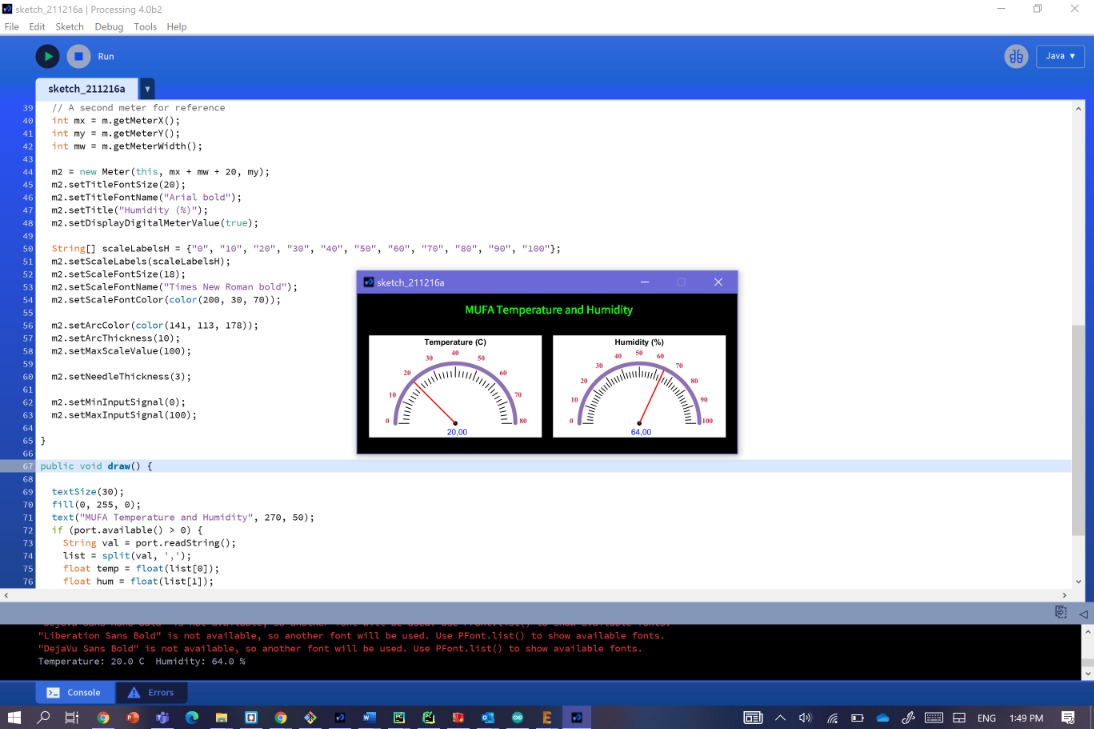
To run the final application, first upload the code in the board using the arduino as the programmer and keep the it connected to the pc. Next, open the processing sketch and modify the serial port name and baud-rate according to your setup and upload the necissary Libraries for the Processing Here I uploaded the Meter and the serial libraries.
And then just click on run

it will shows a Temperature and Humidity meter running with real time data coming from the sensor.
But the thing is, I noticed that the Temp/Hum values on the Interface didn't change until I close the tag and run the code again !!
Pulse monitor
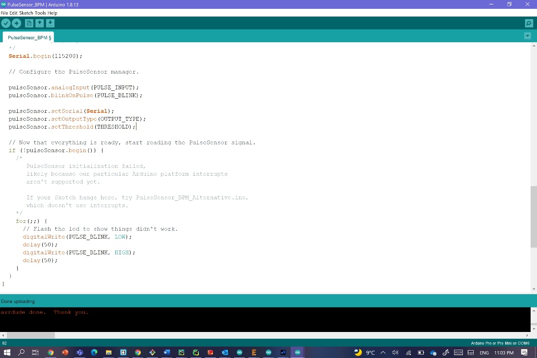
Arduino codeBefore running this program, you have to upload the Pulse Sensor Arduino Sketch the Arduino board. In order for your Arduino board to talk to the Pulse Sensor Amped Visualizer, you will need to change a variable in the Arduino code. The variable is called outputType, and by default it is set to SERIAL_PLOTTER. You need to change it to PROCESSING_VISUALIZER. To make this change, go to the main tab of the Arduino Sketch, and change the variable declairation.
const int OUTPUT_TYPE = PROCESSING_VISUALIZER;
For the code, you can find it in
File>Examples>Pulse sensor Playgroung>PulseSensor_BPM
Processing code
so why not trying to use another input sensor and make a GUI for it.
for that I used the pulse reader and made the same wiring and steps, except for the part that I had to download the zipped file from here. Unzip it, and take the folder called PulseSensorAmpd_Processing_Visualizer and place it in the Documents/Processing folder.
Then open or restart Processing to access the code through your Sketch folder. Select File > Sketchbook...
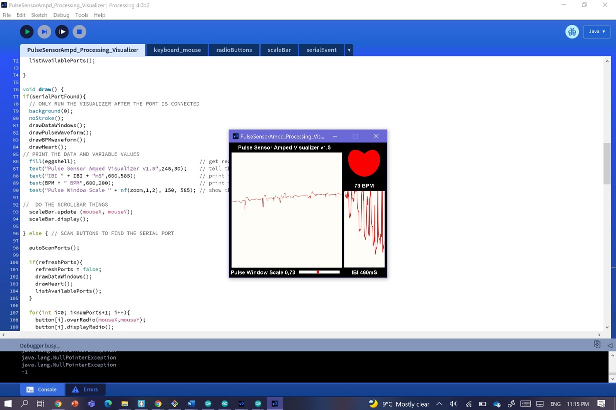
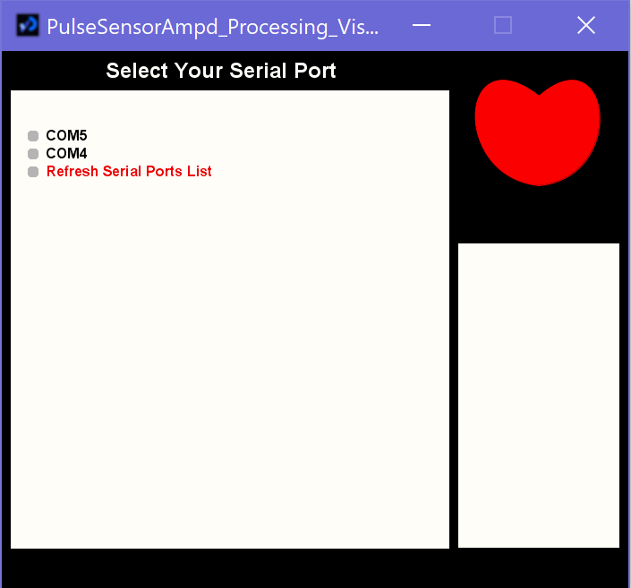
The thing is about this interface is that they give you the list of the available ports with auto-update whenever you plug/unplug USB cables and you get to pick your port. You can also make a note of the port that you used to upload your code in Arduino, since it's the same one. Once you select the right port, you will start seeing hearbeat data!
Manifistation
My Files
Processing pulse readerArduino code; pulse sensor